


 135 / 192

135
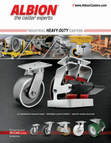
Various bore sizes are avail-
able for FL for use as plain bore
wheels or to be used with keyway
and set screw or with a variety of
bearings. This cast iron
wheel offers 30,000 psi
tensile strength.
Face Diameter “A”
(Inches)
Face Diameter “A”
(Inches)
Flange OD “B”
(Inches)
Flange OD “B”
(Inches)
Face Width “C”
(Inches)
Face Width “C”
(Inches)
O.A. Width “D”
(Inches)
O.A. Width “D”
(Inches)
Hub Length “E”
(Inches)
Hub Length “E”
(Inches)
Approx. Wt.
(LBS)
Approx. Wt.
(LBS)
3
4
1 1-3/8 2-3/16 1-5/8 1-3/16 3/8
9/16
1/4
700 3/4
3
FL0320112
3-1/4 4
1 1-3/8 2-3/16 1-3/4 1-3/16 3/8
19/32
7/32
700 3/4
3
FL0310112
4-1/2 5-1/2 1-9/16 2-3/8 2-1/2 2-1/2 1-15/16 13/16 1/16
1/16
1500
1
9-1/2
FL0410116
4-1/2 5-1/2 1-9/16 2-3/8 2-1/2 2-1/2 1-15/16 13/16 1/16
1/16
1500 3/4
9-1/2
FL0410912
5
6 1-1/8 1-1/2 2-3/16 1-3/4 1-3/16 3/8
11/32 11/32
500 3/4
5-1/4
FL0510112
5-3/8 6-1/8 1-5/16 1-11/16 2-3/16 1-3/4 1-3/16 3/8
13/32
3/32
900 3/4
5
FL0520112
5
6 1-1/8 1-15/16 3-1/4 2-1/2 1-15/16 13/16 15/16
3/8
1000
1
6-1/2
FL0520116
5
6 1-1/8 1-15/16 3-1/2 2-1/2 1-15/16 13/16 15/16
3/8
1000 3/4
6-1/2
FL0520912
6 6-3/4 1-5/8 2 2-3/16 1-3/4 1-3/16 3/8
3/32
3/32
900 3/4
8-1/2
FL0620112
7-1/16 8-3/4 1-3/4 2-3/16 2-3/4 2-5/8 1-15/16 7/16
9/32
9/32
1200
1
12-3/4
FL0720116
7-1/16 8-3/4 1-3/4 2-3/16 3
2-5/8 1-15/16 7/16
9/32
9/32
1200 3/4
12-3/4
FL0720912
8 9-1/2 2 2-1/2 3-1/4
3 1-15/16 1/2
3/8
3/8
1600
1
16-1/4
FL0840116
8 9-1/2 2 2-1/2 3-1/2
3 1-15/16 1/2
3/8
3/8
1600 3/4
16-1/4
FL0840912
10
12 2-3/8 3 3-1/4
3 1-15/16 5/8
1/8
1/8
2000
1
29-1/4
FL1050116
10
12 2-3/8 3 3-1/2
3 1-15/16 5/8
1/8
1/8
2000 3/4
29-1/4
FL1050912
14
16
3 3-5/8 4-1/4 4-1/4 2-7/16 5/8
5/16
5/16
3000 1-1/4
56
FL1460120
14
16
3 3-5/8 4-1/2 4-1/4 2-7/16 5/8
5/16
5/16
3000
1
56
FL1460916
•
Finish:
Gray
enamel
•
Temperature
Range:
Up to
+800°F, consult
factory for high
temperature
requirements
•
Hardness:
Brinell
145
•
Note: Select bear-
ings featured are
recommended for
standard applica-
tions. For special
applications or
alternate bearings
consult factory. See
bearing information
on page 13
•
For customization
& special applica-
tion options, please
consult factory
Single Flange
Hub O.D. “F”
(Inches)
Hub O.D. “F”
(Inches)
Wheel
Number
Straight
Roller (01)
Wheel
Number
Straight
Roller (01)
Wheel
Number
Tapered Roller
(09)
Wheel
Number
Tapered Roller
(09)
Letters match to
chart descriptions
below.
Bore “G”
(Inches)
Bore “G”
(Inches)
Flange Width “H”
(Inches)
Flange Width “H”
(Inches)
Hub Offset “I”
(Inches)
Hub Offset “I”
(Inches)
Hub Offset “J”
(Inches)
Hub Offset “J”
(Inches)
Capacity
(Lbs)
Capacity
(Lbs)
Bearing Size
(Inches)
Bearing Size
(Inches)
5
6
3/4 1-1/2 2-3/16 1-3/4 1-3/16 3/8
11/32 11/32
500 3/4
6
FD0510112
10
12 1-3/4 3 3-1/4
3 1-15/16 5/8
1/8
1/8
2000
1
35
FD1050116
10
12 1-3/4 3 3-1/2
3 1-15/16 5/8
1/8
1/8
2000 3/4
35
FD1050912
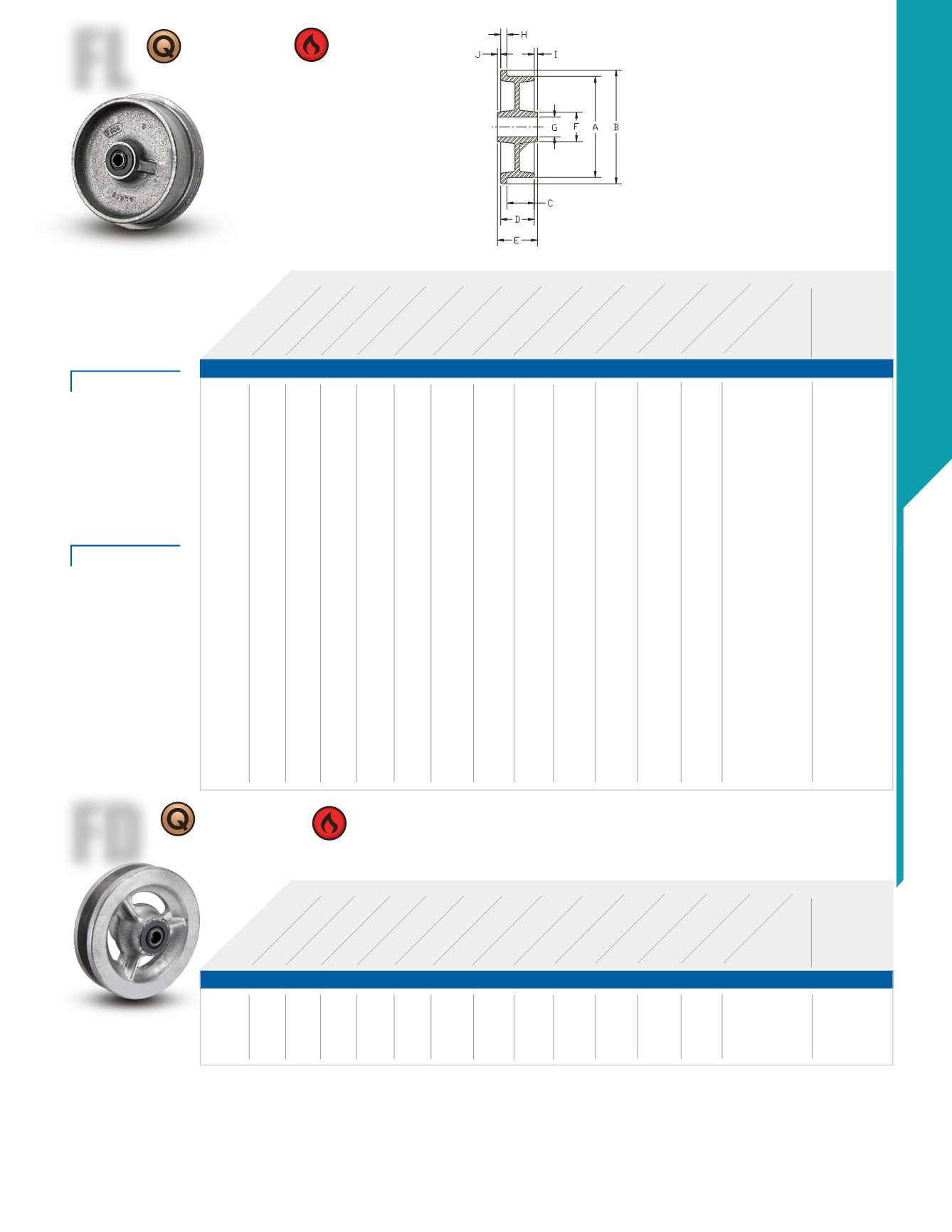
Double Flange
FD
FD offers various bore
sizes for use as plain
bore wheels or to be
used with keyway
and set screw or with a variety
of bearings. This cast iron
wheel offers 30,000 psi tensile
strength. See FL for features
and options.
Premium Quality
Premium Quality
Heat Resistant
Heat Resistant
Single Flange (FL)
Double Flange (FD)
FEATURES
WHEEL OPTIONS
CAST IRON WHEELS • UP TO 3000